Circuit simulation is a vital step in electronics design, as circuit simulators provides the ability to validate electronic circuits before committing to the physical circuit. It also allows for a shorter feedback cycle to quickly iterate on the circuit design. Experimenting with new circuits will be much harder and much more expensive if not for circuit simulators, as many of the components needed for the circuit may not be available at the time or even at a local supplier.
IC design specially takes advantage from circuit simulator, by making custom models for transistors based on the physical characteristics of the transistor of a given fabrication process. For that, it is important to validate the design using circuit simulators before fabrication.
From that I was inspired to program my own circuit simulator, as it sometimes feels like black magic, which it is not. For sure I can solve a circuit using pen and paper, but to turn that to a stream-lined algorithm to be programmed may be a challenge. There is also a lot of edge cases that has to be handled.

Working Principle
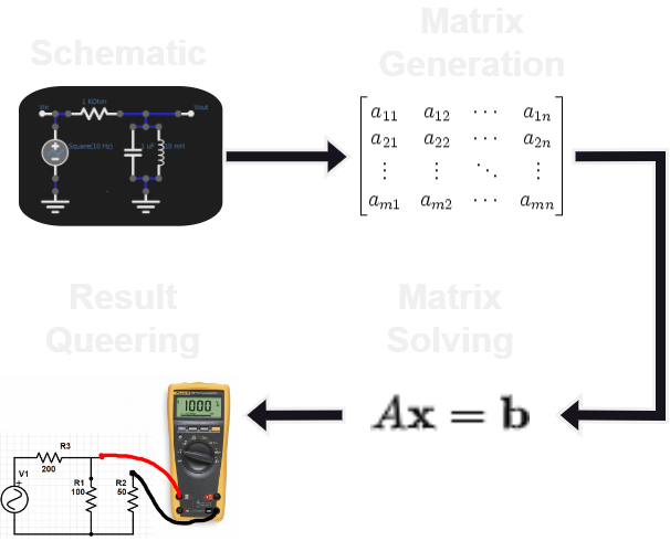
Circuit simulation with all its types is divided into four steps, only the first step is shared between all types of circuit simulations. These steps can be summarized as following:
- Circuit schematic: laying out the circuit with all the components and wires.
- Circuit matrix generation: creating the circuit matrix which describes all the constraints of all the components for the unknown variables (node voltages, currents and other variables). This matrix is derived from the schematic by expressing the constraints of every component in the matrix.
- Matrix solving: calculating the unknown variables by solving the matrix, then propagating the result to the node voltages and components.
- Result queering: Reading a specific result like a node voltage, voltage difference between two nodes or a wire current from the simulation result.
The implementation of these four steps differ slightly between one circuit simulator to another. In matrix generation the constraints of each component are added in the matrix one component at a time. For solving the matrix which is the coefficients matrix of a linear system of equation LU factorization can be used for accurate result, although other linear system solvers exists like the Gauss-Sidel method. Some of the components have non-linear constraints, for that Newton-Raphson method is used to solve the non-linear system in an iterative steps, each step is solving a linear system.
Scope
- DC operating point analysis.
- Time domain analysis (transient analysis).
- AC domain analysis.
- GUI editor with a simple interface.
- Basic fundamental simulation models.
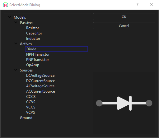
Available Models
Circuit Examples
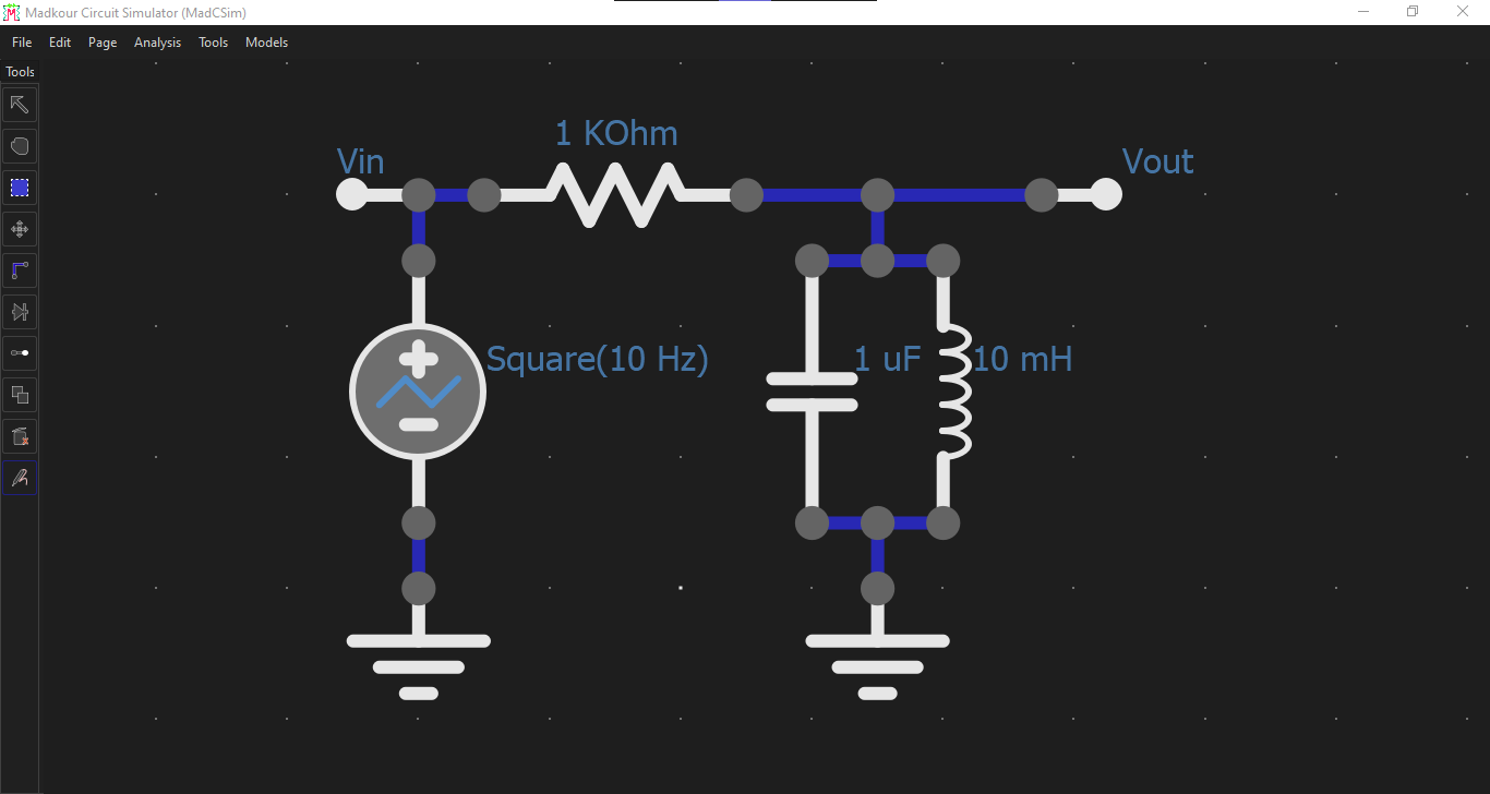
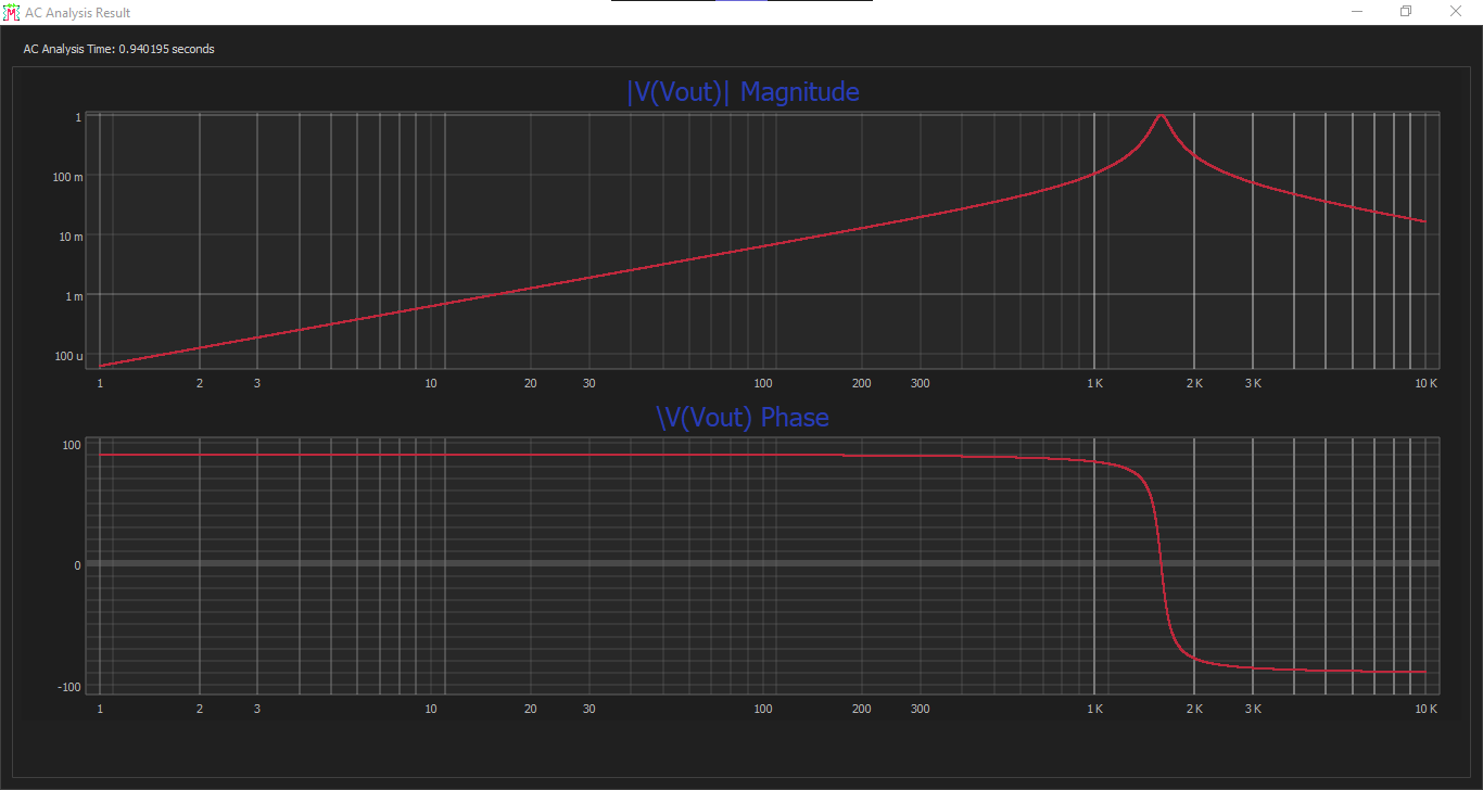
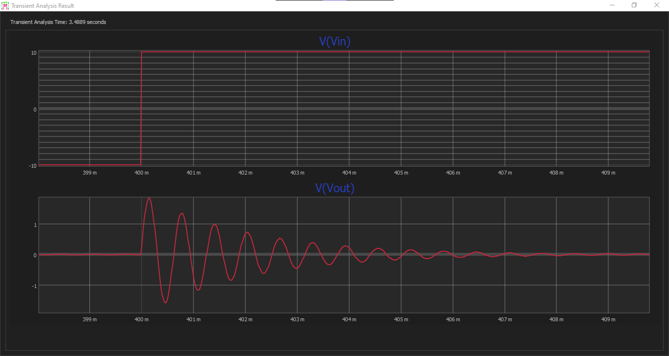
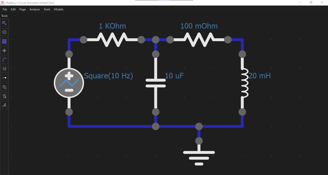
RLC Notch Filter
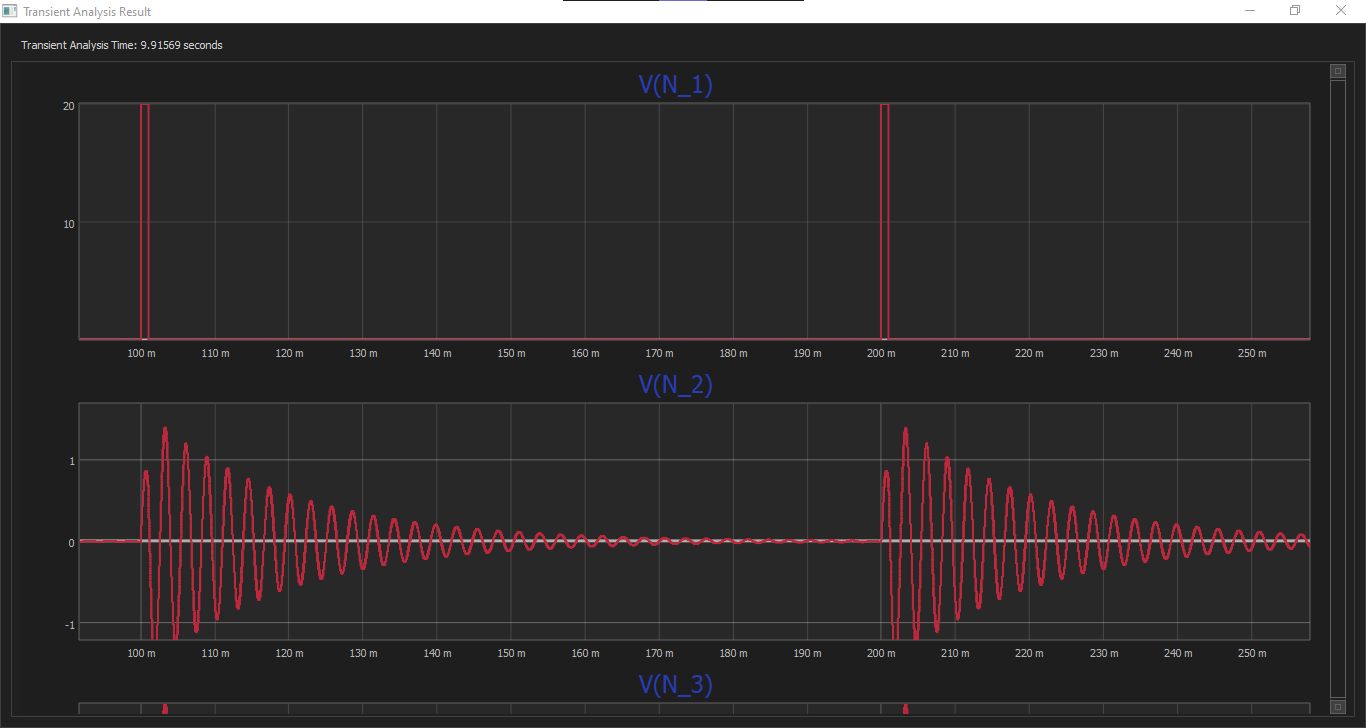
RLC Oscillator Tank
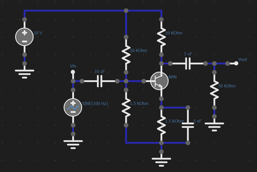
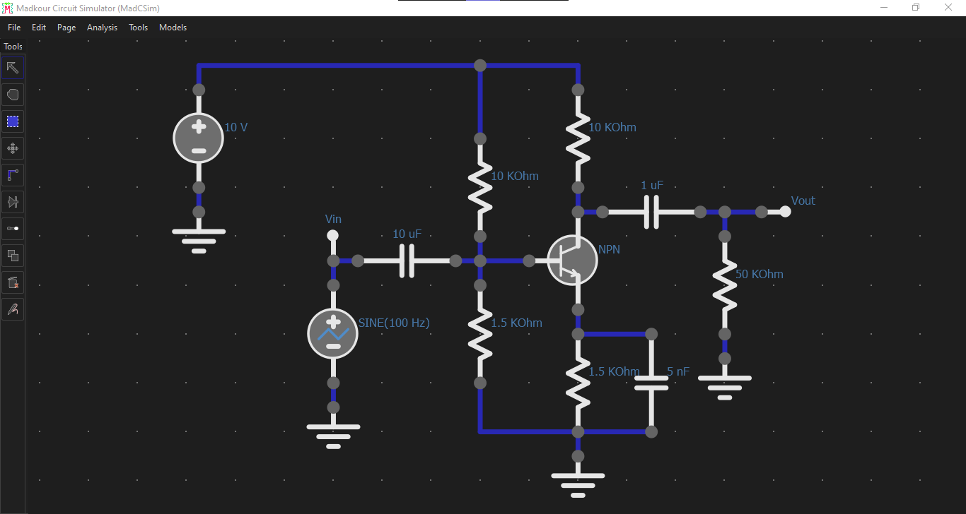
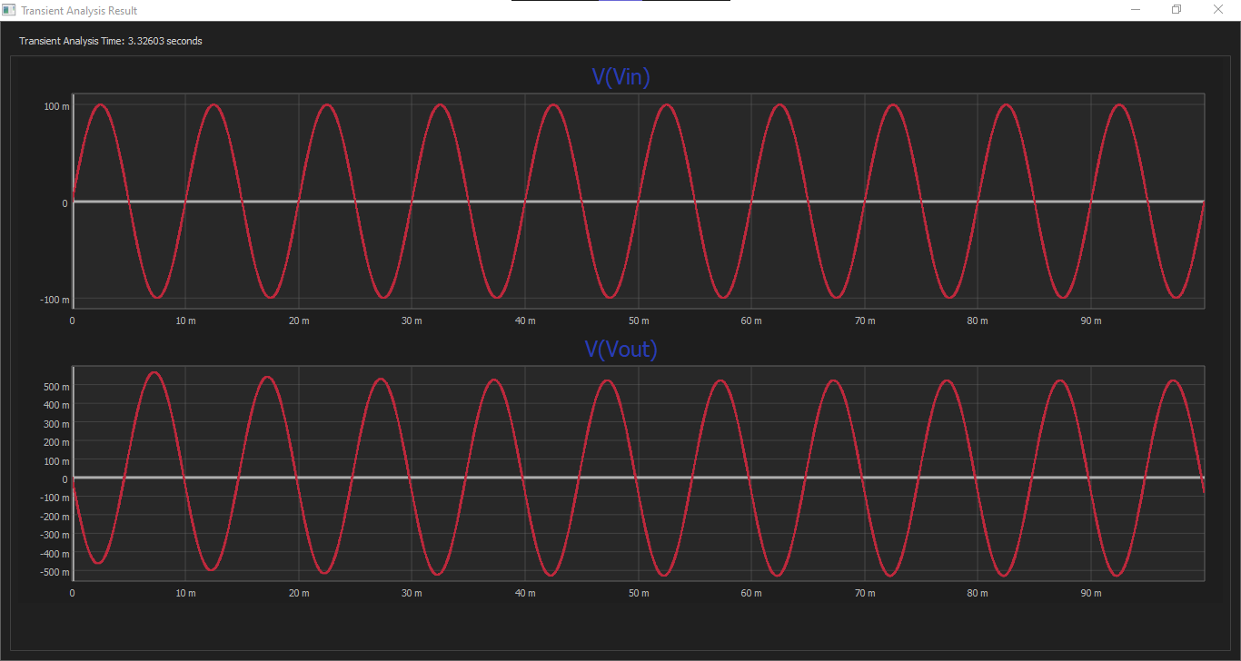
NPN Common Emitter Amplifier
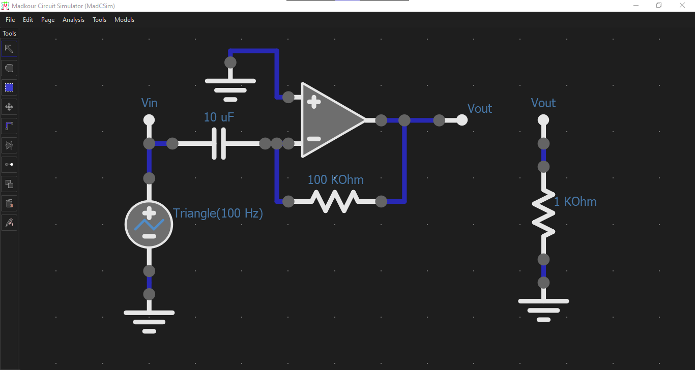
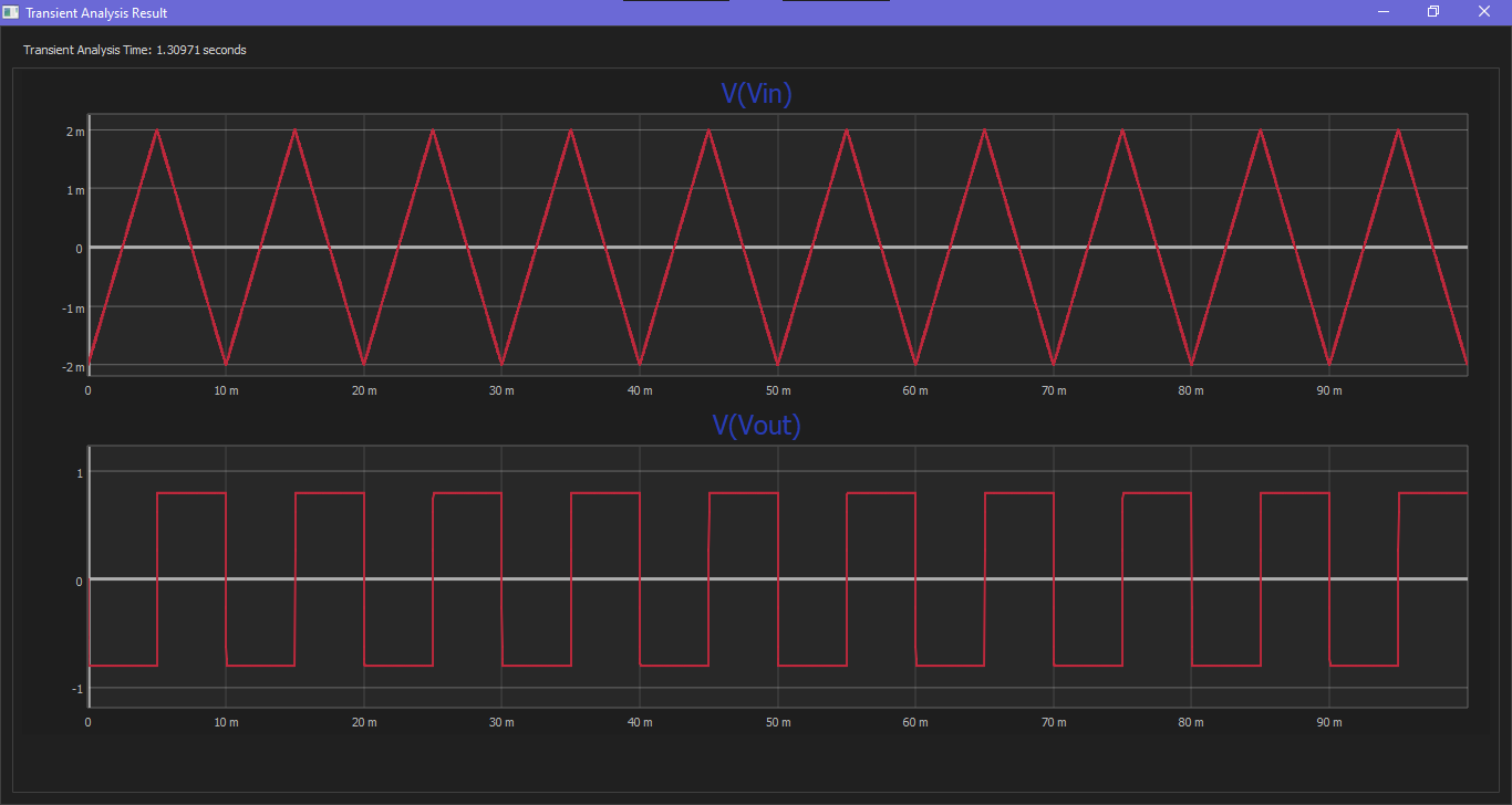
OpAmp Differentiator
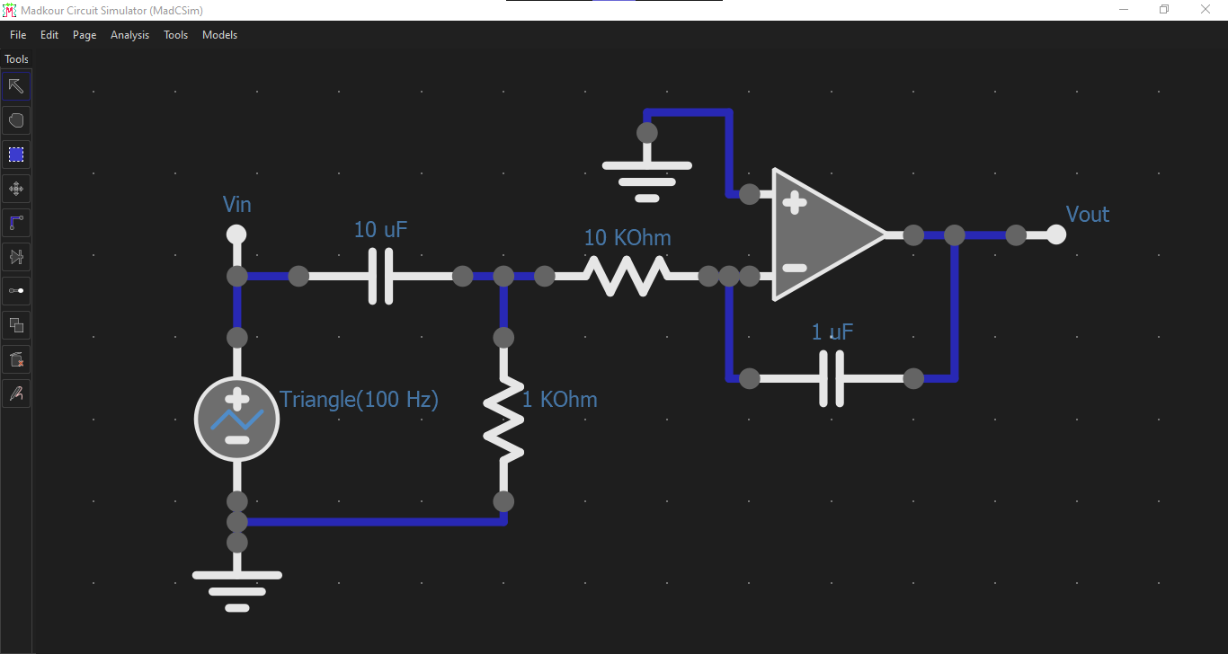
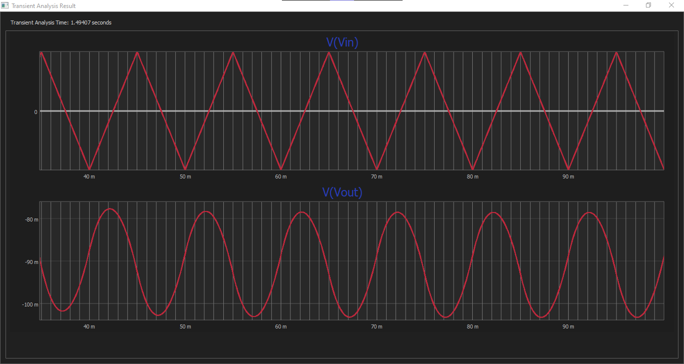
OpAmp Integrator
MadCSim Web App
Download MadCSim Desktop
In conclusion this was good project to explore how to simulate electronic components with algorithms.
References
- Electronic Circuit and System Simulation Methods, Lawrence T. Pillage (1994).